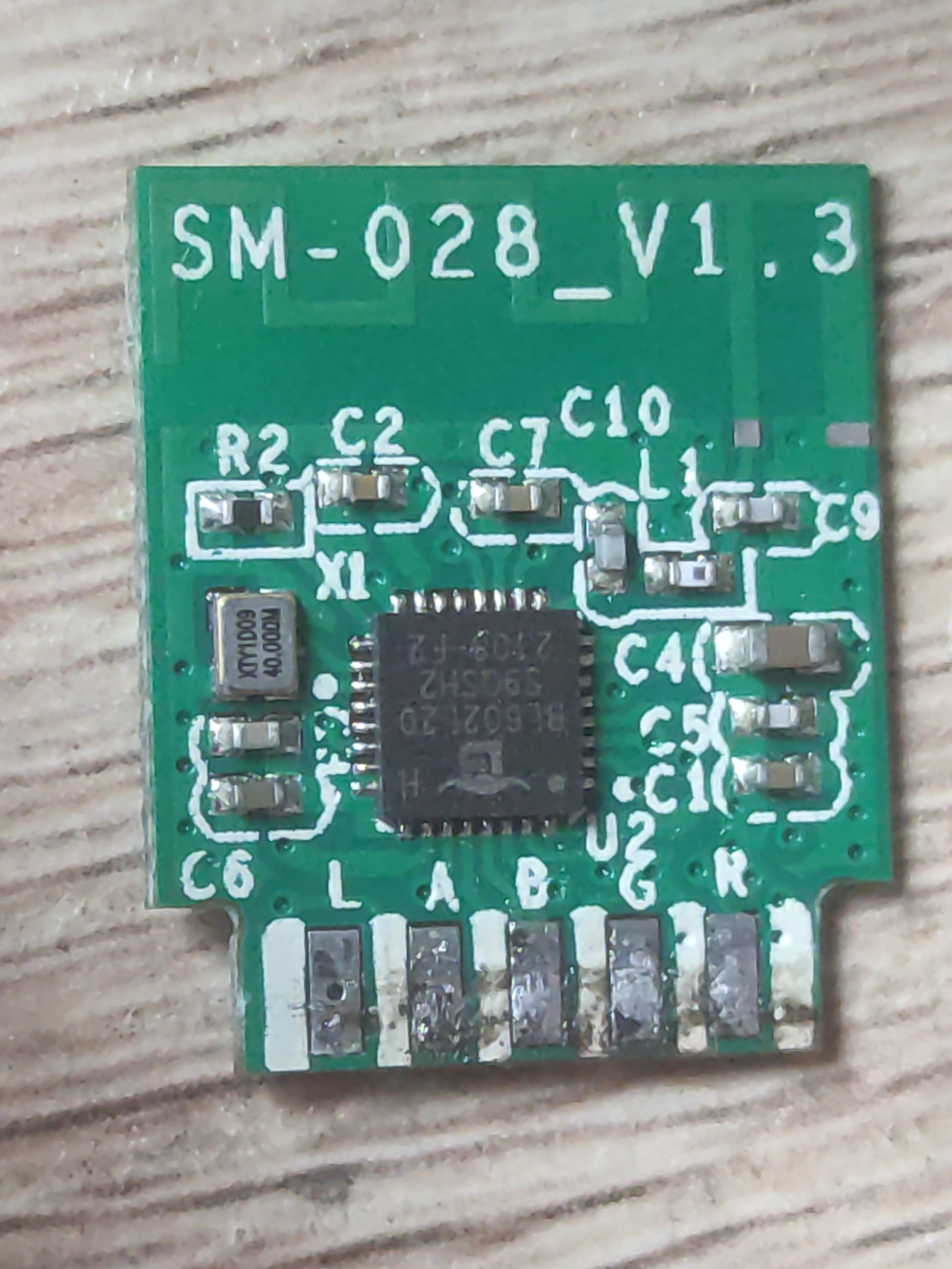
Well, the only active is the BL602, so the pins are likely to correlate closely to the pinouts from the datasheets.
You took these out of something, so knowing where they went is very much a key. We deduce the R G B and the lights of those colors, and they're probably driven from the GPIO pins. It'll be up to you and a microscope and/or meter to find which. If you're feeling really lazy, just write software that configures the candidate pins as outputs and sends them smoke signals that you can identify with a scope. Maybe GPIO 3 gets a burst of 3 pulses and GPIO 4 gets a burst of four and you just poke them with a scope until you find them.
3.3V, GND, TX1, RX1, are surely self-explanatory. BT is likely the Bluetooth antenna.
We won't know if 'A' is 'antenna' or an analog input or just what. To what was it connected?
These boards can be a little frustrating to reverse, owing to one of the very features that makes these chips awesome. There's a huge multiplexor that can be controlled in software so that any pad on the package can be indirected to one of many internal chip functions. For example, Pad GPIO__0 alone can be any of {PAD_GPIO_0 SF2_D1 CLK MIS0/MOSI SIG0 /SIG4 SCL PWM_CH0 - FEM0 or TMS/TCK } just depending on how the MUX is configured. So a scope/VM/circuit trace alone won't tell you the whole story.
Unless the chip is running a modified bootloader, the serial lines are likely key to getting new code onto the chips. Even then, the original design might have those pins N/C as to allow (probably signed)code updates only over WiFi. If this is in some strand of LED lights, it's far more likely that it's meant to be maintained via connection to an internet-connected computer which can send it code blocks or light chase sequences via Bluetooth or Wifi than it is to assume the user of a $6 LED is going to have an available JTAG probe.
L and A might be I2C pins, delivering SCA (arbitration) and SCL (clock).
You might try attaching a logic analyzer to the various pins, capturing any outputs they make, and then feeding them to a SIGROK decoder stack. That would confirm the I2C theory, but only if something was trying to scan for/use I2C while you were capturing it. Clock signals tend to really pop out on a LA trace. I have no real guess what the 22, 17, C, and W pins might be.
Good luck. I look forward to seeing the results of your reverse/forward engineering on /r/bl602 or hackaday or such!